April 17, 2024
Achieving Efficient Heat Flow: PCB Thermal Management Best Practices
Share
BuildWithFlux


A curated collection of PCB and hardware projects crafted by our talented Flux community.
Electric currents generate heat as they pass through resistive elements of a circuit. The higher the resistance of a conductor, the more heat will be generated as current passes through it. Therefore, addressing both electric and thermal parameters in board design is essential for long-term functionality. PCB thermal analysis plays a vital role in the design process, as it can predict thermal flaws and provide an opportunity for circuit redesign. Some key PCB design considerations for improved thermal performance include temperature-sensitive components. Components that are especially sensitive to temperature should be placed in the location with the lowest temperature, such as the bottom of the board.
The simplest way to dissipate heat would be through thermal vias to the cooling system (heat sink or heat pipes). The heat sink draws heat away from the PCB to fins that provide a larger surface area for faster heat dissipation.
Thermal Equivalent Circuits are an analogy of electrical circuits to provide an estimation of the flow of heat in a design. They work because the underlying equations for the transfer of thermal energy and electrical energy are similar enough. With the analogies, we can calculate the heat transfer within the PCB.
Equivalent Equations
I = V1-V2/R => Q = T1-T2/Rt
Where:
I is the current (A)
V is the voltage (V)
R is the electrical resistance
Q is the heat flow (W)
T is the junction temperature (°C)
Rt is the thermal resistance (°C/W)
Similarly, equivalent thermal resistance in series and parallel also follows the same equations for electrical resistance.
Thermal impedance measures the sum of thermal resistance and thermal contact resistance of a material. This value can be found in the component datasheet for integrated circuits and ranges from 20 °C/W for low-power amplifiers or ICs, to as high as ~200 °C/W for powerful microprocessors. The operating temperature can be determined by multiplying the component’s power consumption by its thermal impedance.
T = Z*P
Where:
T is the component temperature (°C).
P is the power usage of the component (W)
Z is the thermal impedance (°C/W)
When your PCB generates significant heat, choosing a substrate with superior thermal conductivity is crucial. Ceramics are an excellent option due to their high thermal conductivity and adjustable mechanical properties, which help manage mechanical stress during thermal cycling. Adding a metal core to the board or increasing copper below components, such as adding a plane layer, can also enhance heat dissipation.
When designing PCBs, the importance of effective thermal management cannot be overstated. High-power components generate significant heat, and without proper dissipation, the performance and longevity of the circuit boards can be compromised. One effective method to manage this heat is by using a heat sink. A heat sink helps to draw heat away from critical components, improving the overall thermal performance of the PCB.
Thermal relief is also design feature used in electronic circuit boards to manage heat dissipation from components that generate significant heat during operation. It helps to prevent overheating and ensures the reliability and longevity of the components.

There are two main configurations for thermal relief:
PCBs are the backbone of modern electronics, and ensuring they operate within safe thermal limits is crucial. Circuit boards that overheat can lead to component failure and reduced reliability. This is why thermal resistance and thermal impedance are important parameters to consider in PCB design. By carefully selecting materials and employing efficient cooling techniques, such as integrating cooling fans, the thermal performance of PCBs can be significantly enhanced.
PCB thermal simulation enables designers to predict thermal management issues, ensuring optimal heat dissipation. By simulating different layouts and thermal solutions, designers can avoid costly physical iterations and achieve a thermally efficient design from the outset.
Thermally conductive materials, such as certain ceramics, can greatly improve the heat dissipation capabilities of circuit boards. Additionally, incorporating thermal vias and using thermally conductive paste can further aid in managing the heat generated by high-power components. Cooling fans are another essential element in thermal management, ensuring that heat is effectively removed from the PCB and dissipated into the surrounding environment.
PCB design requires careful consideration of thermal management techniques. By utilizing heat sinks, thermally conductive materials, and cooling fans, designers can create circuit boards that operate efficiently and reliably, even under demanding conditions. Proper thermal analysis and simulation are key to achieving optimal performance and preventing overheating issues in PCBs.


If you're a lover of smart home devices, you're likely buzzing with excitement over Arduino's recent collaboration with Silicon Labs. We are too, and we’re even more excited to bring the power of this collaboration to life on Flux. As of today, we’re excited to announce that engineers can fully design Arduino-based Matter boards with Flux.

We’ve been so amazed with the ways you’ve used Copilot to brainstorm, debug, and conduct part research that we’ve compiled some of our favorite prompts you can copy and paste, or modify for your own use!

Learn how smart vias in Flux automates the selection, placement, and configuration of vias during the PCB design process. This automation reduces the manual effort involved in via placement and significantly lowers the risk of misalignment and other common errors associated with traditional via management.


This blog post explores the RS485 communication standard, renowned for its ability to facilitate long-distance, multidrop networking with enhanced noise immunity, making it a preferred choice for industrial settings. Dive into the post to understand RS485's key features and advantages over older protocols.

Dive into the world of DIY Arduino projects, learning everything from choosing the right board to creating advanced home automation systems.
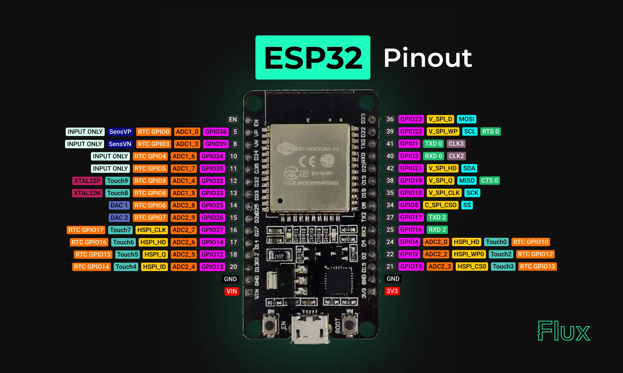
Looking for a comprehensive guide to ESP32 pinout? Check out our article that covers everything you need to know about the ESP32's pins, including digital, analog, PWM, and Strapping pins. Perfect for beginners and experts alike, our guide will help you understand the ESP32's pinout and how to use it in your projects.

Explore more than 20 new Flux Copilot prompts for hardware design. Accelerate brainstorming, component selection, validation and design review to streamline your PCB design.


This blog will explore functional block diagrams, their pivotal role in system design, the symbiotic relationship with ladder logic, structured text, and the broader realm of PLC programming. Why FBDs are so important within complex systems.